Stand Mixer Design Evaluation
Overview
For ME41 (Engineering Design II) our team tore down a "Kitchen in the Box" 3.2 quart stand mixer and evaluated it like a real product instead of a textbook problem. Once it was open, three subsystems were doing the actual work: a spur-and-planetary gear train, ball bearings sitting in a plastic housing, and a tilt-head hinge with a safety interlock. None of it came with manufacturer specs, so most of the numbers below are things we measured, counted, or back-calculated ourselves, then ran through free-body diagrams, life calculations, and FEA from Shigley's.
Gear train
Compact spur plus planetary train that trades motor speed for mixing torque.
- Measured the paddle at 165 RPM about the bowl from slow-motion video, then counted every tooth in the train (13-tooth motor pinion through a 95, 9, and 75-tooth spur set into a 41-tooth ring and 13-tooth planet).
- Train value e = (13 x 9) / (95 x 75) = 0.0164, which back-calculates the motor to roughly 10,050 RPM. The 300 W motor plate then gives a no-load torque near 0.29 N-m.
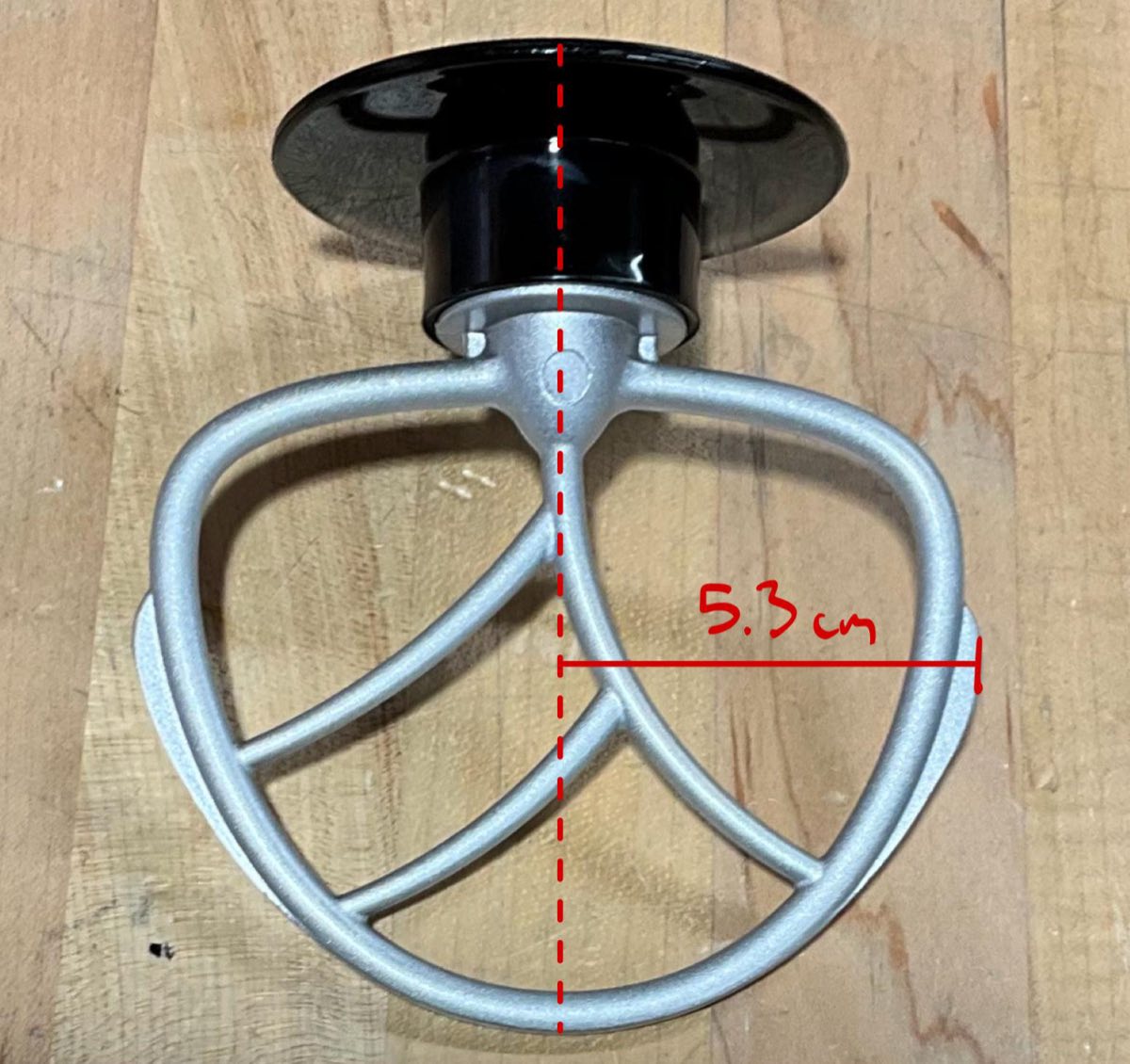
- The planetary stage adds 2.15x, for a total 28.3:1 reduction, about 8.1 N-m at the paddle and roughly 153 N at the beater edge (r = 5.3 cm).
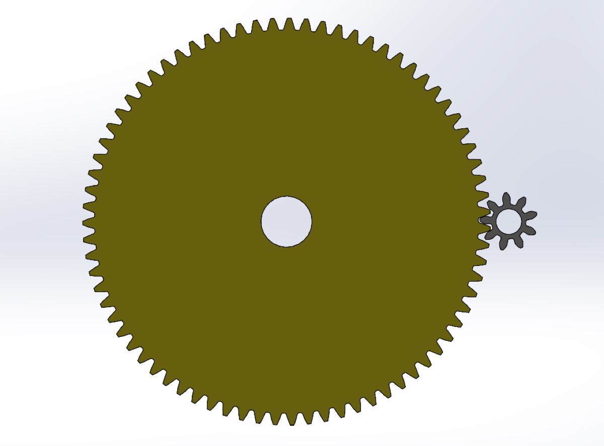
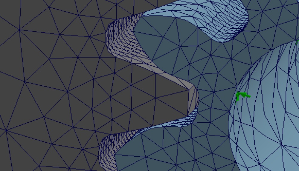
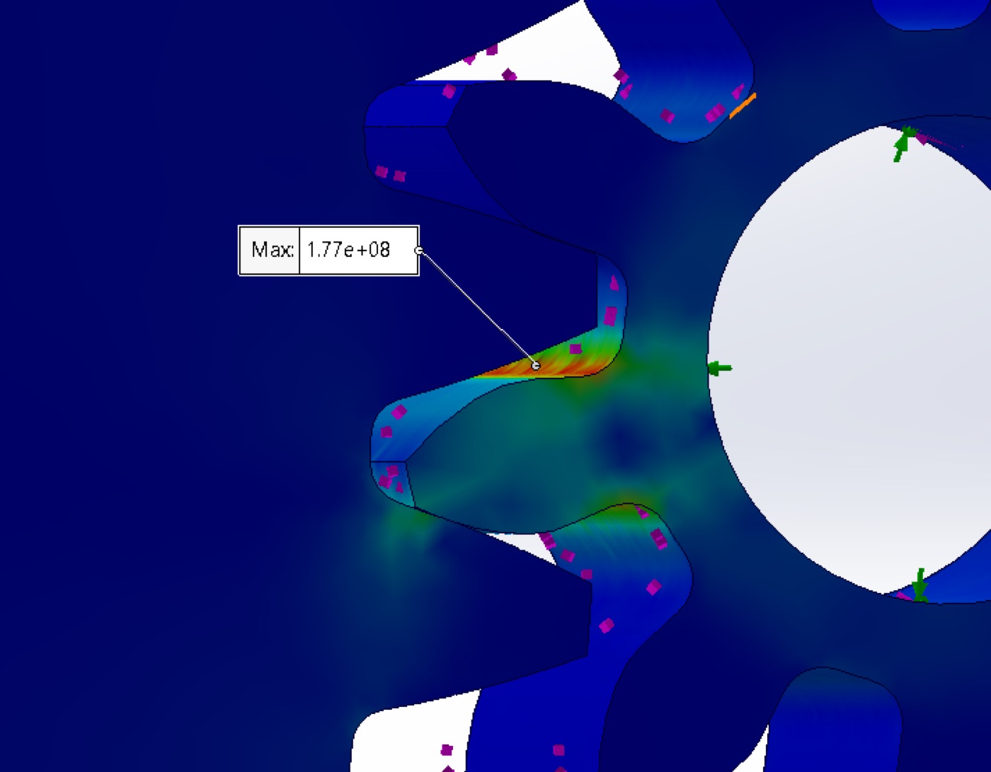
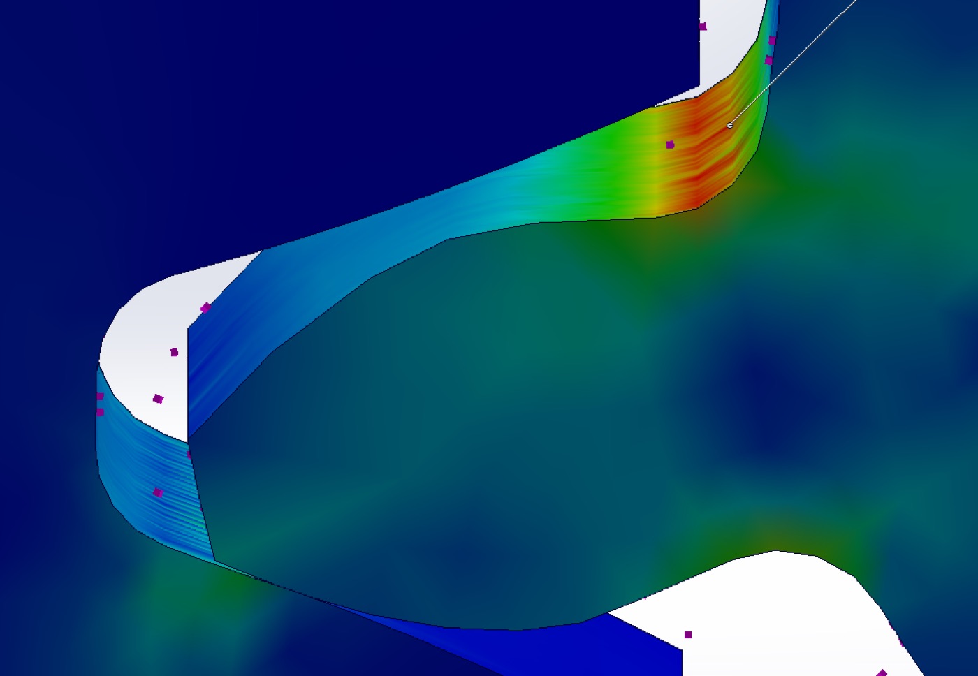
- Modelled the gears in Onshape (20 degree pressure angle, 1.25 mm module, one-third root fillet, 0.02 cm backlash), then ran a SolidWorks motion study and a static FEA with AISI 4130 steel and PA6 nylon, control-meshed at the tooth contacts under 2.09 N-m.
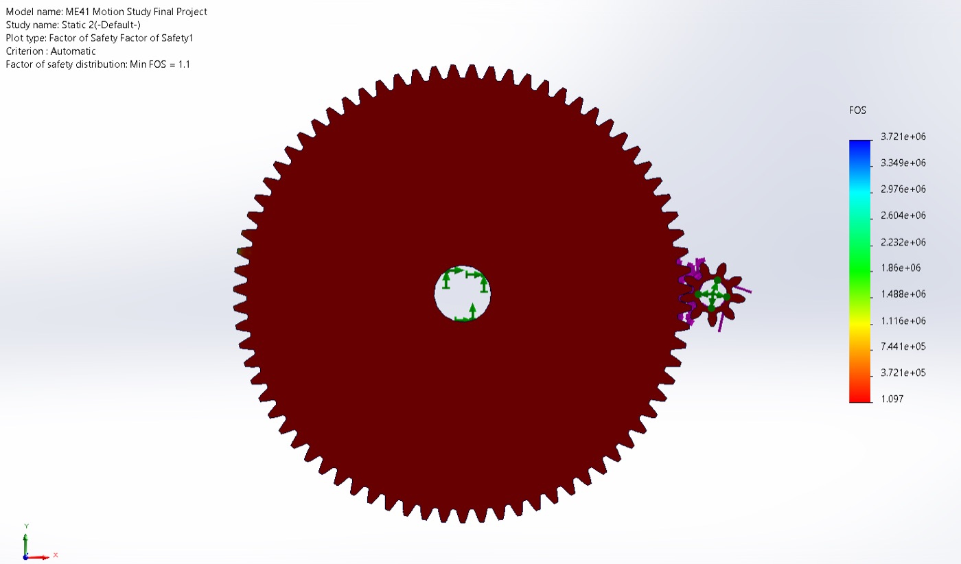
- The steel gears come out at a reasonable stress and the nylon runs well below that, but factor of safety is only just above 1 in the most loaded spots, so there isn't much room for overload or material variation.
Bearings
A single deep-groove ball bearing carrying the belt and gear loads on the intermediate shaft.
- Identified the part as a 608 deep-groove ball bearing (8 x 22 x 7 mm, dynamic rating 3.3 kN) sitting in an injection-moulded glass-filled nylon housing.
- Traced the load path: belt tension to pulley to intermediate shaft at 17.4 N-m, giving a 2320 N belt radial load plus a 253 N gear separating force, or 2570 N radial and 257 N axial at the bearing.
- The ABMA equivalent load works out to 2714 N, so L10 = (C / P) cubed x 1e6 = 1.8 million revolutions, about 182 hours at 165 RPM (136 to 234 hours across a plus or minus 300 N band on the load rating).
- That short life is driven almost entirely by the constant belt tension. Housing compliance, press-fit creep, grease breakdown, and start-stop cycling all pull the real figure lower, so the bearing is likely to go loose or noisy before any gear fails.
Hinge and latch
The tilt-head lock, its torsion spring, and the safety switch that cuts power when the head is up.
- A button push slides a travel rod back so its thin section clears the curved latch slots, the head swings through 60 degrees, and a compression spring re-engages the thick section to lock it. The same motion trips a switch that kills motor power whenever the head is raised.
- Modelling the head as a rigid body (about 2.0 kg, centre of mass 0.20 m from the hinge), head weight alone gives a 3.9 N-m moment and a hard 50 N user push raises the total to 11.4 N-m.
- The torsion spring (2.2 mm wire, 8 active coils) supplies about 0.79 N-m of restoring torque at around 910 MPa wire stress against a 2050 MPa music-wire yield, a factor of safety near 2.3.
- Latch contact pressure runs 3 MPa in normal use and 10 MPa under the hard push, both well below yield, so wear in the slots rather than strength sets the life. Travel-rod axial stress is about 2 MPa, negligible.
Gear train CAD & FEA
SolidWorks static study of the driven spur pair under 2.09 N-m, control-meshed at the tooth contacts.
What the analysis showed
Bottom line, the mixer does what it needs to: roughly 28 to 1 reduction, about 8 N-m at the beater, bearings that are sized right, and a hinge that locks safely off one button. What's thin is margin, not function. The nylon gears sit barely above a factor of safety of 1, bearing life is capped by how hard the belt pulls, and the plastic housing just makes the real numbers worse than the theoretical ones. Fixing it means easing off the belt tension, stiffening the bearing support, and giving the nylon gears more margin.
Full report
Product Design Evaluation: Stand Mixer
ME41 Project 2 report · PDF · 38 pages